

The Fundamentals of Outdoor Broadband Wireless – Part 2: Weatherproofing Your Network – How to Overcome Rain, Snow, and Extreme Temperatures
- Joe Wargo

- Oct 7, 2025
- 4 min read
Outdoor broadband wireless networks are built to deliver carrier-grade performance across harsh environments — but weather is their constant adversary. From torrential rain to summer heat and freezing winters, environmental conditions can dramatically affect signal strength, uptime, and hardware lifespan.
For municipal IT leaders, utilities, and broadband operators, weatherproofing isn’t optional; it’s the difference between a reliable public-safety backbone and a network outage that halts operations.
This article explores how engineering, frequency planning, and redundancy come together to make outdoor wireless truly all-weather-ready.
1. How Weather Impacts Wireless Performance
Weather affects radio signals in different ways depending on frequency, distance, and link design.
Rain Fade (High-Frequency Microwave Links)
At frequencies above 11 GHz — especially 18 GHz, 23 GHz, and 80 GHz (E-band) — raindrops absorb and scatter signal energy. This phenomenon, known as rain fade, can reduce link margin and throughput.
• Short, dense rain events can cause brief attenuation spikes.
• Prolonged downpours can lead to sustained degradation if fade margins are inadequate.
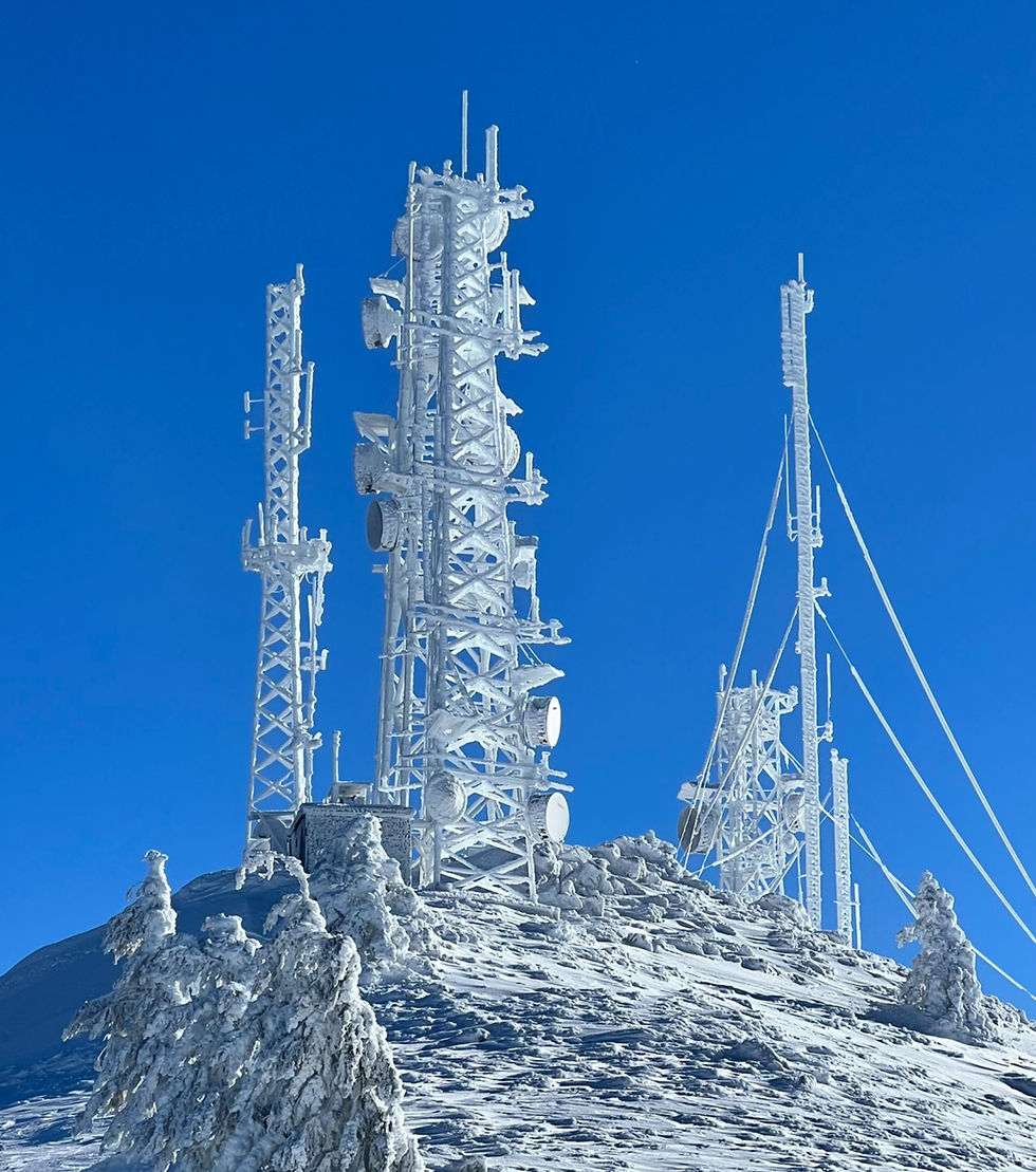
Snow and Ice
Snow generally has less attenuation than rain, but ice accumulation on antennas or radomes can distort the signal path or detune polarization. Proper radome design and hydrophobic coatings can mitigate buildup.
Temperature and Humidity
Extreme heat affects radio electronics, amplifiers, and power supplies, while cold snaps cause component contraction and potential condensation inside enclosures. High humidity accelerates corrosion if seals fail.
Wind
Strong winds create alignment drift on towers or poles, especially with larger parabolic antennas. Even minor movement can alter received power enough to trigger modulation drops or link instability.
2. Designing for All-Weather Resilience
Mitigating these conditions starts with engineering discipline — choosing the right frequency, equipment, and environmental protection for the site. A properly engineered broadband wireless backhaul network can provide 99.999% predictable reliability.
Select the Right Frequency Band
• < 11 GHz Licensed Bands (6, 7, 11 GHz): Excellent rain tolerance, long-range, ideal for critical backhaul.
• 18–23 GHz: High capacity, moderate weather resilience for metro and short-haul links.
• 70/80 GHz (E-Band): Delivers multi-gigabit throughput but requires line-of-sight and shorter distances (2 mi or less).
Best Practice: Use dual-band or multi-band links (for example, 11 GHz + 80 GHz) so the high-frequency path handles primary data and the lower band provides a weather-resilient backup. Most multi-band microwave backhaul links are 10Gbps full duples with a 1Gbps full duplex redundancy.
Engineer for Fade Margin
To ensure the success of a fixed wireless backhaul implementation, it is crucial to perform accurate wireless path calculations and design the system accordingly. Every link design should include at least 20–30 dB of fade margin in high-rain regions to maintain carrier availability of 99.999%. Tools such as ITU-R P.530 provide regional rain-rate data to model precise margins. Microwave path analysis provides factual data that is used to design a precise path, including the selection of wireless equipment, antennas, cabling, system settings, power settings, frequencies, antenna and tower heights, and polarizations. These calcualtions and design engineering should be done by a professional wireless integrator.
Harden Your Hardware
• Use IP-67/68-rated enclosures with conformal-coated PCBs.
• Add gasketed weather seals and breathable membrane vents to prevent moisture intrusion.
• Specify industrial-grade power supplies and cables rated from –40 °C to +60 °C.
• For freezing climates, use radome heaters or automatic de-icing elements.
Wind-Rated Mounting and Alignment
Antenna mounts and towers must be rated for local wind zones. Implement:
• Heavy-duty mounts with torque-balanced brackets.
• Antenna alignment monitoring (AAM) sensors that alert technicians when tilt or azimuth changes.
• Periodic torque inspections as part of preventive maintenance.
3. Power Systems Built for the Elements
Even the most robust link fails without power. Outdoor sites should include:
• DC distribution and surge protection to prevent lightning or transient damage.
• Hardened UPS systems capable of extended runtime during grid outages.
• Solar-hybrid or battery backup for remote or rural deployments.
• Heated battery enclosures in cold regions to maintain charge efficiency.
Reliability means planning for environmental extremes and utility failures simultaneously. Important fact: the number one cause of outdoor wireless system failures and downtime isn’t faulty radios or poor line-of-sight. It’s inadequate or unreliable power infrastructure. More about Power Systems here
4. Monitoring and Proactive Maintenance
Smart networks don’t just survive storms — they anticipate them.
• Integrate SNMP and network monitoring to track RSSI, fade margin, and temperature metrics in real time.
• Use predictive analytics to trigger alerts when thresholds approach environmental limits.
• Schedule seasonal inspections before peak weather periods.
• Employ drone or visual inspections for tower ice or damage after major storms.
This proactive model ensures issues are resolved before they impact uptime.
5. Case Example – Municipal Resilience in Action
A mid-size, city public works department deployed redundant 11 GHz + 80 GHz microwave rings to connect water facilities and traffic intersections. During heavy Texas thunderstorms, the 80 GHz paths temporarily attenuate, but the 11 GHz links automatically maintain connectivity with no service interruption.
By designing for rain fade and temperature resilience, the city achieved 99.999% link availability and avoided costly fiber extensions — saving months of trenching and permitting.
6. Key Takeaways for CIOs and Utility Leaders

Weather-proofing isn’t just about hardware — it’s a system-wide design philosophy combining physics, materials, and monitoring.
7. The Road Ahead
As we move toward Part 3 – Interference and Spectrum Management, we’ll shift from the physical environment to the invisible one: the radio spectrum itself. Learn how to design for clear, interference-free connectivity even in dense RF environments.


Comments